Machine screws are specified by three main dimensions: diameter, thread pitch (or threads per inch), and length. These dimensions follow either the Imperial (Unified Thread Standard, UTS) or Metric system. Below is an overview of the most common machine screw sizes, how they’re designated, and what each part of the designation means.
1. Imperial (Unified Thread Standard) Sizes
In the UTS system, machine screws are identified by a gauge number (for smaller diameters) or by the nominal diameter in fractions of an inch (for larger screws). The gauge (also called “size number”) roughly corresponds to the major diameter of the screw, while the threads per inch (TPI) defines the thread pitch.
1.1. Gauge & Diameter
-
Gauge numbers start at #0 (the smallest common size) and increase to #14.
-
As the gauge number goes up, so does the diameter.
-
A #0‑80 screw has a major diameter of approximately 0.060″. A #8‑32 screw is about 0.164″ in major diameter.
-
-
Fractional sizes begin at ¼″‑20 (0.250″ diameter) and go up from there (e.g., 5/16″‑18, 3/8″‑16).
1.2. Common UTS Machine Screw Sizes
| UTS Size | Major Diameter (in) | TPI (Coarse) | Thread Class* |
|---|---|---|---|
| #0‑80 | 0.060 | 80 | 2A / 3A |
| #1‑64 | 0.073 | 64 | 2A / 3A |
| #2‑56 | 0.086 | 56 | 2A / 3A |
| #3‑48 | 0.099 | 48 | 2A / 3A |
| #4‑40 | 0.112 | 40 | 2A / 3A |
| #5‑40 | 0.125 | 40 | 2A / 3A |
| #6‑32 | 0.138 | 32 | 2A / 3A |
| #8‑32 | 0.164 | 32 | 2A / 3A |
| #10‑24 | 0.190 | 24 | 2A / 3A |
| ¼″‑20 | 0.250 | 20 | 2A / 3A |
| 5⁄16″‑18 | 0.312 | 18 | 2A / 3A |
| 3⁄8″‑16 | 0.375 | 16 | 2A / 3A |
*Thread Class “2A” (external) and “3A” (external, tighter tolerance) are common for machine screws. Many fasteners will simply be specified as Class 2.
1.2.1. Fine vs. Coarse Threads
-
The table above lists coarse threads (e.g., #8‑32 has 32 TPI).
-
Fine threads (e.g., #8‑36) exist but are less common for general machine screw applications. Fine threads have more TPI (tighter pitch) and are often used in precision assemblies.
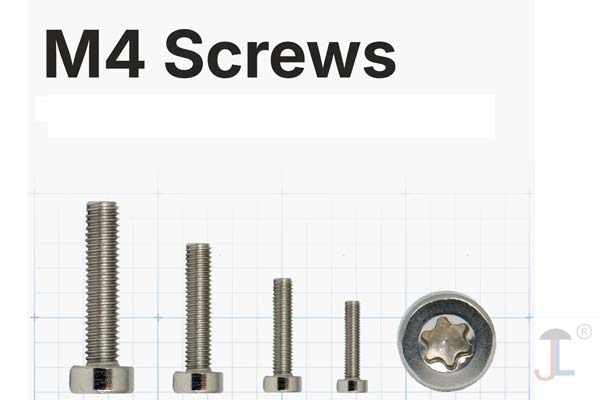
2. Metric Machine Screw Sizes
In the Metric system, machine screws are designated by “M” followed by the nominal major diameter in millimetres, a lowercase “×”, and the thread pitch in millimetres. For example, M3 × 0.5 indicates a 3 mm diameter screw with a 0.5 mm thread pitch.
2.1. Metric Diameter & Pitch
-
Nominal diameter: M1.6, M2, M2.5, M3, M4, M5, M6, M8, M10, M12, etc.
-
Standard (coarse) pitches for common diameters:
Metric Size Major Diameter (mm) Standard Pitch (mm) M1.6 1.6 0.35 M2 2.0 0.40 M2.5 2.5 0.45 M3 3.0 0.50 M4 4.0 0.70 M5 5.0 0.80 M6 6.0 1.00 M8 8.0 1.25 M10 10.0 1.50 M12 12.0 1.75 -
Fine pitches (less common) might be M3 × 0.35, M4 × 0.5, M5 × 0.5, M6 × 0.75, etc., used when a finer adjustment or higher tensile strength is needed.
2.2. Common Metric Machine Screw Sizes
| Designation | Diameter (mm) | Pitch (mm) | Thread Type |
|---|---|---|---|
| M1.6 × 0.35 | 1.6 | 0.35 | Coarse |
| M2 × 0.40 | 2.0 | 0.40 | Coarse |
| M2.5 × 0.45 | 2.5 | 0.45 | Coarse |
| M3 × 0.50 | 3.0 | 0.50 | Coarse |
| M4 × 0.70 | 4.0 | 0.70 | Coarse |
| M5 × 0.80 | 5.0 | 0.80 | Coarse |
| M6 × 1.00 | 6.0 | 1.00 | Coarse |
| M8 × 1.25 | 8.0 | 1.25 | Coarse |
| M10 × 1.50 | 10.0 | 1.50 | Coarse |
| M12 × 1.75 | 12.0 | 1.75 | Coarse |
Note: Metric length is usually measured from the flat bearing surface under the head to the end of the screw.
3. Length Specification
Once you determine diameter and pitch, the third parameter is length:
-
Imperial: Length is measured in inches from the underside of the head to the tip of the screw (e.g., ¼″‑20 × ¾″ means a ¼″ diameter, 20 TPI coarse-threaded, ¾″ long).
-
Metric: Length in millimetres from under the head to the end (e.g., M4 × 0.70 × 16 means 4 mm major diameter, 0.7 mm pitch, 16 mm long).
Lengths typically increment in:
-
Imperial: 1/8″, 3/16″, ¼″, 5/16″, etc.
-
Metric: 4 mm, 6 mm, 8 mm, 10 mm, 12 mm, and so on.
4. Thread Pitch & Classes
-
Coarse threads are standard for most machine screws. They’re stronger (larger thread depth) and easier to mate.
-
Fine threads have more threads per unit length (smaller pitch). They allow finer adjustment and higher tensile stress due to more engaged threads. Fine threads are often used in precision instruments, automotive applications, or where vibration-resistance is critical.
-
Thread classes (e.g., 2A/2B, 3A/3B in UTS) define tolerance/fit.
-
Class 2A/2B is standard fit (“free running” engagement).
-
Class 3A/3B is a tighter fit (used for more critical assemblies).
-
In Metric, fit tolerance is often given as “6g” (external) and “6H” (internal) for a normal fit.
5. Examples of Full Designations
-
Imperial Example:
-
#8‑32 × ½″, 18‑8 Stainless Steel, Phillips Pan Head
-
#8 gauge diameter (~0.164″)
-
32 TPI (coarse thread)
-
½″ length (from under head to tip)
-
Material & head style as additional specs
-
-
-
Metric Example:
-
M5 × 0.8 × 20 mm, Class 8.8, Phillips Flat Head
-
5 mm diameter
-
0.8 mm pitch
-
20 mm length
-
8.8 grade (tensile strength)
-
Flat‑head countersunk style
-
-
6. How to Choose the Right Machine Screw Size
-
Determine the hole or tapped thread:
-
If you have a tapped hole, match the pitch and diameter exactly (e.g., tapped M4 × 0.7).
-
If using a clearance hole, choose a screw size that fits the clearance diameter (e.g., a 5 mm clearance hole for an M5 screw).
-
-
Load requirements:
-
Higher loads may benefit from screw grades (e.g., Grade 8.8 or 10.9 in Metric; Grade 5 or 8 in Imperial).
-
-
Material & environment:
-
Stainless, zinc‑plated, black oxide, or specialized coatings for corrosion resistance.
-
-
Length needs:
-
Ensure enough engagement into the threaded component. A rule of thumb is at least one thread diameter of engagement in mild steel; more in softer materials.
-
7. Quick Reference Tables
7.1. Imperial Thread Table (Coarse)
| Size | Dia. (in) | TPI | Common Lengths (in) |
|---|---|---|---|
| #4‑40 | 0.112 | 40 | ¼″, 5⁄16″, 3⁄8″, ½″, ¾″ |
| #6‑32 | 0.138 | 32 | 3⁄16″, ¼″, 3⁄8″, ½″, 1″ |
| #8‑32 | 0.164 | 32 | ½″, 5⁄8″, ¾″, 1″, 1¼″ |
| #10‑24 | 0.190 | 24 | ½″, ¾″, 1″, 1½″, 2″ |
| ¼″‑20 | 0.250 | 20 | ½″, ¾″, 1″, 1½″, 2″ |
7.2. Metric Thread Table (Coarse)
| Size | Dia. (mm) | Pitch (mm) | Common Lengths (mm) |
|---|---|---|---|
| M2 × 0.4 | 2 | 0.40 | 4, 6, 8, 10, 12, 16 |
| M3 × 0.5 | 3 | 0.50 | 6, 8, 10, 12, 16, 20 |
| M4 × 0.7 | 4 | 0.70 | 8, 10, 12, 16, 20, 25 |
| M5 × 0.8 | 5 | 0.80 | 10, 12, 16, 20, 25, 30 |
| M6 × 1.0 | 6 | 1.00 | 12, 16, 20, 25, 30, 40 |
| M8 × 1.25 | 8 | 1.25 | 16, 20, 25, 30, 40, 50 |
8. Tips & Best Practices
-
Always specify full designation: “M4 × 0.7 × 12 mm, Class 8.8, Pan Head Phillips” or “#8‑32 × ¾″, Grade 5, Zinc Plated, Phillips Flat Head.”
-
Check thread engagement: For tapped holes, ensure at least one to two diameters of engagement. In softer materials (e.g., aluminum), aim for two diameters.
-
Match materials: Avoid combining dissimilar metals (e.g., stainless steel screw in aluminum tapped hole) without proper lubrication or threadlocker to prevent galling.
-
Use thread gauges or pitch gauges: If you’re identifying an unknown screw, a set of screw gauges will help you confirm diameter and pitch.
Summary
-
Imperial (UTS) machine screws: Designated by gauge (#0‑#14) or fractional diameter (¼″‑20, 5⁄16″‑18, etc.) plus TPI.
-
Metric machine screws: Designated by “M” + diameter (mm) × pitch (mm), followed by length (mm).
-
Length: Measured from under the head to the tip—imperial in inches, metric in millimetres.
-
Thread types: Coarse (standard) vs. fine (higher TPI or smaller pitch).
-
Thread class/tolerance: UTS uses classes 2A/2B (standard) or 3A/3B (tight). Metric uses fits like 6g/6H.
Knowing how to read and specify machine screw sizes ensures you select the correct fastener for fit, strength, and compatibility in your application. If you have a tapped hole, always match diameter and pitch exactly. For clearance holes, choose a drill size suitable for the major diameter of your screw. Proper length and material choice complete the selection, giving you the right machine screw for any assembly.